

USB Connector Wiring: Pin Assignments and Cable Guide
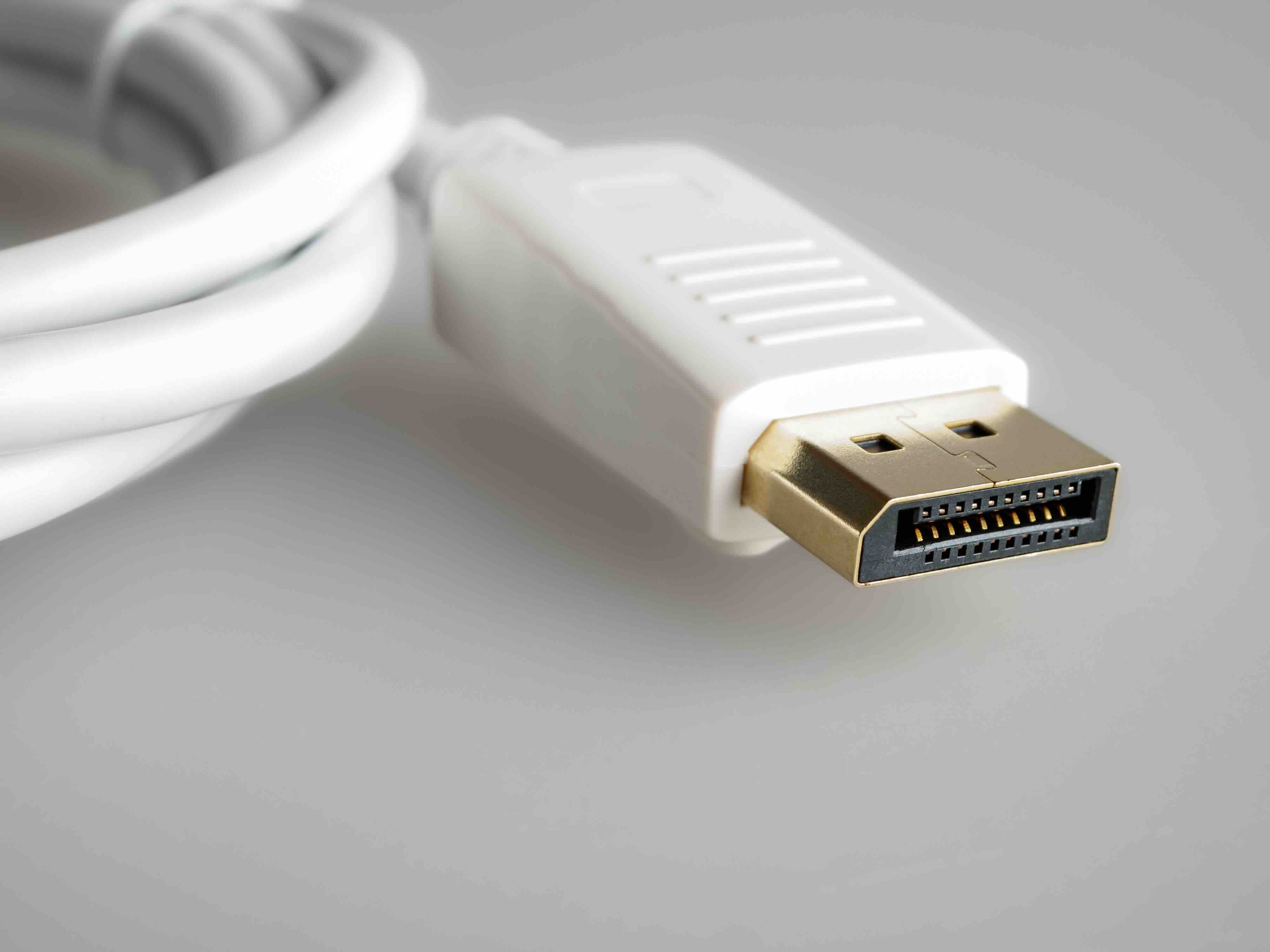
USB Connector Wiring Explained: A Complete Guide to How USB Cables Are Built and Why It Matters
Most people plug in a USB cable without a second thought. It works, the device charges, files transfer, and life moves on. But underneath that simple plug-and-play experience is a surprisingly precise wiring architecture that determines speed, power delivery, signal integrity, and compatibility. Understanding USB connector wiring is genuinely useful, whether you are sourcing cables for a workspace, setting up a data center, or just trying to figure out why one cable charges your laptop at full speed while another barely trickles. This guide breaks it all down in plain terms so you can make smarter decisions about the cables and connectors you rely on every day.
What Is USB Connector Wiring and Why Does It Matter
USB, or Universal Serial Bus, was designed to standardize the connection between computers and peripheral devices. The wiring inside a USB cable is what makes that standard possible. At its core, a USB cable contains a set of conductors, each assigned a specific function: power delivery, data transfer, grounding, and in newer standards, additional signaling channels. The number and arrangement of those conductors change depending on the USB version and connector type. Getting the wiring wrong, or using a cable built to lower tolerances, means lost speed, unreliable charging, or outright device failure. That is not a small thing when you are running a business or building out a professional setup.
The Basic USB Wiring Color Code and Pin Assignments
Standard USB cables follow a color coding convention that has remained fairly consistent across Type-A and Type-B connectors. Inside the cable jacket, you will typically find four wires, each with a designated role based on color. This structure applies to USB 2.0 and earlier configurations. The arrangement is straightforward once you know what to look for.
- Red -- VBUS (Power, +5V)
- White -- D- (Data Negative)
- Green -- D+ (Data Positive)
- Black -- GND (Ground)
The red wire carries the positive supply voltage, which is typically 5 volts in standard USB connections. Black is the ground return path. White and green are the differential data pair, and they work together to carry signals using a balanced transmission method that reduces noise interference. This pairing is critical to maintaining signal quality, especially over longer cable runs. Even minor damage or poor shielding on those data lines can introduce errors and slow down transfer rates significantly.
USB 3.0 and Beyond: More Wires, More Speed
When USB 3.0 arrived, the wiring architecture got considerably more complex. To achieve the jump in data throughput, the specification added additional wire pairs dedicated to SuperSpeed data transmission. A USB 3.0 cable contains the original four wires from USB 2.0 plus two additional twisted pairs for SuperSpeed data, along with a drain wire for shielding. That brings the total to nine conductors in a standard USB 3.0 Type-A to Type-B cable. USB 3.1 and USB 3.2 expanded on that even further, and USB4 introduced a new level of complexity tied closely to the USB-C connector format. More conductors means more precise manufacturing tolerances and better shielding requirements. Cheap cables often cut corners here, and the result is real-world performance loss that users notice immediately.
USB-C Wiring: The Most Complex Connector Yet
USB-C is the current standard connector for modern devices, and its internal wiring is significantly more involved than anything that came before it. The USB-C connector has 24 pins, and the cable that connects two USB-C ports can carry power, data, video, and audio simultaneously depending on how it is wired and what protocols it supports. Key wire groupings inside a full-featured USB-C cable include the following.
- VBUS lines for power delivery up to 240W under USB PD 3.1
- SuperSpeed differential pairs for data transmission
- SBU lines for alternate mode signaling such as DisplayPort or Thunderbolt
- CC lines for connection detection, orientation, and power negotiation
- D+ and D- for backward-compatible USB 2.0 data
The reversible design of USB-C is made possible by duplicating certain signal paths across the connector. The cable itself detects orientation automatically through the CC pins and routes signals accordingly. This is elegant engineering, but it also means that passive cables and active cables perform very differently. An active USB-C cable contains electronics built into the connector housing to boost signal strength over longer distances. Passive cables are simpler but have limitations on length and bandwidth. Knowing which type you need matters a great deal in professional AV and IT installations.
Shielding and Twisted Pair Design: The Unsung Heroes
Signal integrity in USB cables comes down largely to how well the internal wiring is protected from electromagnetic interference. Quality USB cables use individually shielded twisted pairs, where each data pair is twisted together and wrapped in its own foil shield before being bundled inside an overall braid shield and cable jacket. This layered approach minimizes crosstalk between signal pairs and blocks external interference from motors, power lines, and other nearby cables. Cheaper cables skip one or more of these shielding layers, which is why they tend to fail at longer lengths or in electrically noisy environments. For professional deployments, the shielding specification of a cable is just as important as its speed rating.
Common Drawbacks and Wiring-Related Failures
Even well-designed USB cables can fail over time, and the failure almost always traces back to the wiring. The most common issues include broken drain wires that cause intermittent grounding problems, damaged differential pairs from repeated bending near the connector, cold solder joints at the pin terminations, and inadequate strain relief that allows movement to stress the internal conductors. Cables that are not rated for the current they carry can also become a safety issue, particularly with USB-C Power Delivery at higher wattages. Selecting cables built to the correct specification for your application is the most straightforward way to avoid these problems entirely.
Practical Tips for Choosing the Right USB Cable
When selecting a USB cable for any application, whether it is for charging, data transfer, display output, or a combination of all three, a few practical principles will serve you well. Match the cable specification to the use case rather than grabbing whatever is available. Verify that the cable supports the USB version your device requires. For USB-C cables carrying high-power loads, look for cables rated to the appropriate amperage. Check for certification marks where applicable. And consider cable length carefully, since longer runs demand better shielding and sometimes active signal boosting. Investing in the right cable upfront is always more cost-effective than troubleshooting mysterious connectivity failures later.
USB Wiring Standards and Backward Compatibility
One of the most practical aspects of USB wiring design is how the standards committee handled backward compatibility. Because USB 3.0 cables retained the original four-wire configuration from USB 2.0 in addition to the new SuperSpeed pairs, older devices work fine on newer cables and ports. The protocol negotiates speed at the time of connection based on what both ends of the cable support. USB-C handles this through the CC pin negotiation process, which is why a USB-C cable plugged into a USB 3.2 port on one end and a USB 2.0 device on the other will still function, just at the lower speed. Understanding this hierarchy helps clarify why not every USB-C cable is a USB4 cable, and why reading the spec sheet before purchasing matters.
Why Monoprice Should Be Your Source for USB Cables and Connectivity Solutions
When you understand what goes into USB connector wiring, the quality gap between a well-built cable and a generic option becomes impossible to ignore. Monoprice has spent years engineering cables that meet real-world performance demands without the inflated price tags that come from brand overhead alone. Every conductor count, shielding layer, and pin termination in a Monoprice USB cable is built to spec, which means you get predictable, reliable performance whether you are provisioning a single workstation or hundreds of endpoints across a facility. If you are ready to stop guessing and start sourcing cables you can trust, explore the full range of high-performance USB cables and connectivity solutions at Monoprice and see what professional-grade wiring looks like at a price that actually makes sense for your budget.
Frequently Asked Questions About USB Connector Wiring
What are the four wires inside a standard USB 2.0 cable?
A standard USB 2.0 cable contains four wires: red for VBUS power at 5 volts, black for ground, white for the D- data signal, and green for the D+ data signal. These four conductors handle both power delivery and data communication in all USB 2.0 connections.
How many wires are inside a USB 3.0 cable?
A USB 3.0 cable contains nine conductors. It includes the original four wires from USB 2.0 plus two additional twisted pairs for SuperSpeed data transmission in each direction, along with a drain wire used for shielding purposes.
Why does USB-C have so many pins?
USB-C has 24 pins to support a wide range of functions including power delivery, high-speed data, video output, and audio, all through a single reversible connector. The pin duplication across the connector's two orientations also enables the reversible insertion that USB-C is known for.
Does cable length affect USB performance?
Yes. Longer cables introduce more resistance and signal degradation. USB 2.0 has a maximum passive cable length of 5 meters, while USB 3.0 is typically limited to around 3 meters for passive cables. Active cables with built-in signal boosters can extend these limits reliably.
What is the difference between a passive and an active USB cable?
A passive USB cable contains only conductors and shielding with no electronics inside. An active USB cable includes circuitry built into the connector housing that boosts the signal, allowing it to maintain performance over longer distances or at higher data rates.
Why does shielding matter in USB cables?
Shielding protects the internal signal wires from electromagnetic interference generated by nearby devices, power cables, and motors. Without adequate shielding, data errors increase, transfer speeds drop, and cables become unreliable in environments with significant electrical noise.
Can any USB-C cable support video output or Thunderbolt?
No. Only USB-C cables that are wired to support alternate modes and that meet the required bandwidth specifications can carry DisplayPort video or Thunderbolt signals. Standard USB-C charging cables are often not wired to support these protocols.
What causes USB cables to fail over time?
The most common causes of USB cable failure include damaged conductors from repeated bending, cold solder joints at pin terminations, broken shielding or drain wires, and inadequate strain relief near the connector housing. Poor-quality materials accelerate all of these failure modes.
Are all USB-C cables compatible with USB Power Delivery?
No. USB Power Delivery requires cables rated for the specific wattage being transferred. Higher power levels such as 60W, 100W, or 240W require cables built with conductors sized for the current load. Using an undersized cable at high wattage creates a safety hazard.
How do I know if a USB cable meets the spec I need?
Look for cables that clearly state the USB version they support, include certification marks where applicable, and specify the maximum data transfer rate and power delivery rating. Purchasing from a reputable manufacturer with documented specifications is the most reliable way to ensure compatibility.


