

USB Cable Wiring: What Every User Should Know
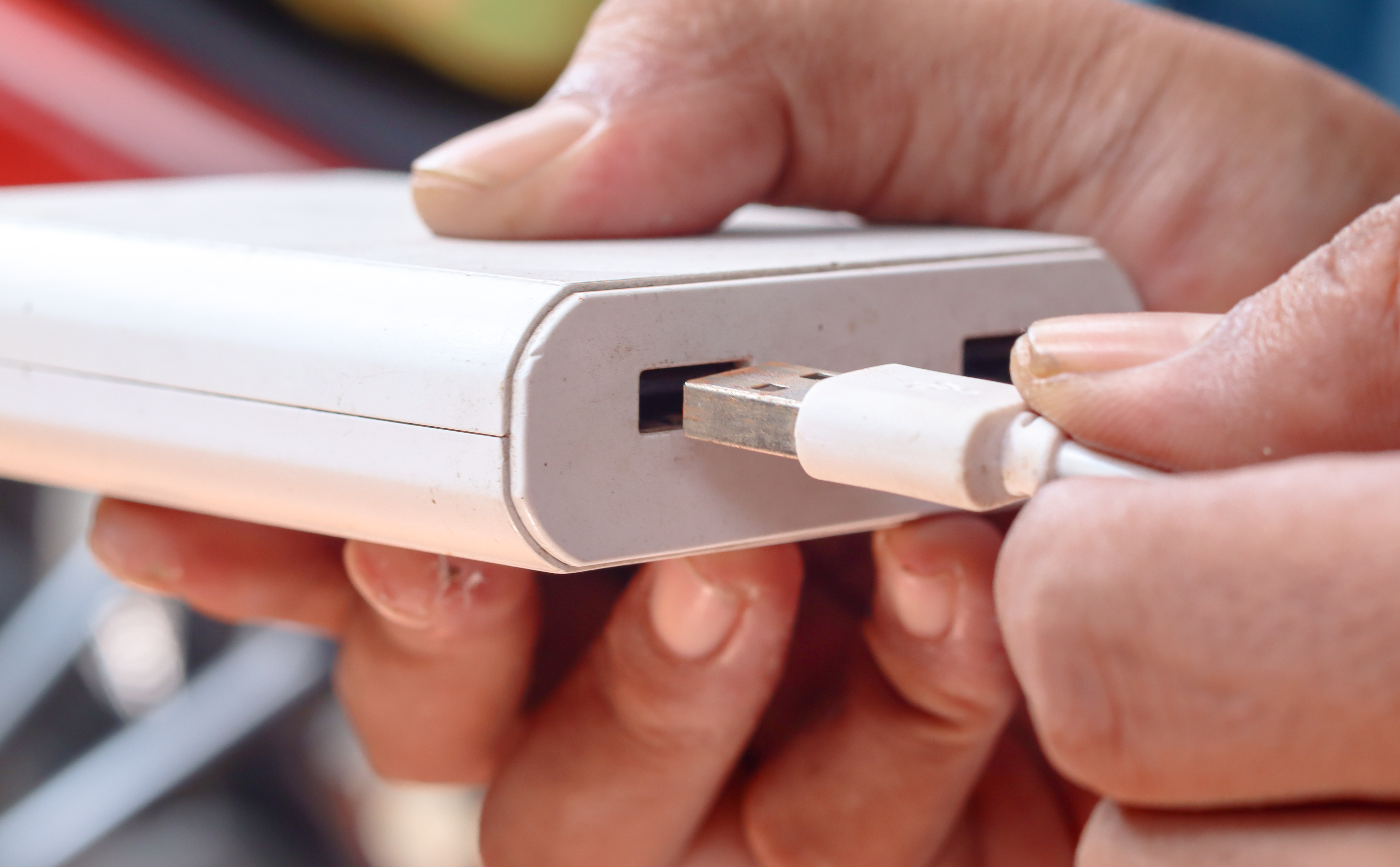
USB Cable Wiring Explained: What Every User Should Know
USB cables are everywhere. You use them to charge your phone, transfer files, connect peripherals, and power everything from desk lamps to hard drives. But most people have no idea what is actually happening inside the cable. And honestly, that is fair. Most of the time it just works. Except when it does not, and then you are left wondering why your fast charger is charging slowly, or why your device is not transferring data at the speed it should. Understanding USB cable wiring is not just a technical curiosity. It is practical knowledge that helps you buy smarter, troubleshoot faster, and avoid a lot of unnecessary frustration. So here is a clear, grounded look at how USB cables are actually wired, what each wire does, and why it matters more than most people realize.
The Basic Anatomy of a USB Cable
At its core, a USB cable is a bundle of conductors enclosed in insulation and shielding. The exact number of wires depends on the USB type, but the original USB 2.0 standard uses four wires. Those four are the foundation that most people interact with daily, even now. The wires are color coded to help with identification during manufacturing and repair. Standard USB 2.0 wiring follows this structure:
- Red wire carries VBUS, the positive power line at five volts DC
- Black wire is the ground return for power
- White wire is Data Minus, also written as D-
- Green wire is Data Plus, also written as D+
That red and black pair handles power delivery. The white and green pair handles data signaling. Simple in concept, but the execution matters enormously when you start pushing higher voltages or faster data rates through that same physical space.
How USB Power Delivery Works Through the Wiring
The VBUS line, that red wire, carries the voltage from a power source to the connected device. In basic USB 2.0 applications this is five volts at up to 500 milliamps, which gives you 2.5 watts of power. Fine for mice, keyboards, and slow charging. Not fine for modern smartphones or laptops. USB Power Delivery, or USB PD, changes that equation dramatically. By using a dedicated communication channel, compatible cables and chargers negotiate higher voltages and current levels, potentially reaching up to 240 watts with USB PD 3.1. But here is where the wiring becomes critical. A cable that looks identical on the outside might have thin, low-gauge conductors that cannot handle the current without generating heat, voltage drop, or worse. The gauge of the power conductors, measured in AWG, directly determines how much current the cable can safely carry over a given length. Thicker conductors, lower AWG numbers, handle more current. Cheap cables often cut corners here.
Data Wires and High-Speed Signaling
The D+ and D- lines in USB 2.0 carry differential signaling, where data is transmitted as the voltage difference between the two wires rather than a single line relative to ground. This approach is noise-resistant and efficient. USB 2.0 maxes out at 480 Mbps in Hi-Speed mode. USB 3.0 and beyond introduced additional wire pairs to hit faster speeds. A USB 3.2 Gen 2 cable includes the original four wires plus additional SuperSpeed transmit and receive pairs, and in some configurations, multiple lanes. USB4 cables, which share the physical USB-C connector, go even further with tightly controlled impedance-matched differential pairs capable of 40 Gbps. The wiring inside those cables is significantly more complex and the requirements for shielding, pairing, and termination are much stricter. This is why a cheap USB-C cable might charge fine but fail at high-speed data transfer. The connector fits, but the internal wiring simply is not engineered for that use case.
The Role of Shielding and Ground Wires
Shielding is what separates a reliable cable from one that causes signal degradation or interference problems in a demanding environment. USB cables typically use one or more shielding layers, a foil shield, a braided shield, or both. The foil provides consistent coverage against high-frequency electromagnetic interference. The braid adds mechanical durability and additional shielding effectiveness. In USB 3.x and USB4 cables, individual wire pairs are often shielded separately before being grouped together inside an overall shield. This is called individually shielded pairs, and it prevents crosstalk between adjacent data lines. Drain wires run alongside the shields and connect them to ground, giving interference a low-resistance exit path out of the cable. When you pay more for a quality cable, a meaningful portion of that cost is going into the shielding architecture. It is not visible from the outside, but the difference is real under load.
USB-C Wiring: More Pins, More Capability
The USB-C connector introduced a 24-pin configuration that expanded what a single cable connection can do. In addition to power and USB data lines, the USB-C pinout includes Configuration Channel pins, which handle USB PD negotiation and orientation detection, Sideband Use pins for alternate mode signaling, and additional power and ground contacts for higher current. Alternate modes, such as DisplayPort over USB-C or Thunderbolt 3 and 4, repurpose some of those pins to carry completely different signal types. A Thunderbolt 4 cable uses the USB-C connector but the internal wiring and active electronics inside the cable assembly are engineered to entirely different specifications. Not every USB-C cable supports every mode. The wiring inside determines what the cable can actually do, not just the shape of the connector at either end.
Common Wiring Problems and What They Cause
Most USB cable failures trace back to a few recurring wiring issues. Knowing what they are helps you diagnose problems faster:
Broken or intermittent ground connection causes erratic device behavior and charge interruptions
Thin power conductors cause excessive voltage drop, especially over longer cable lengths
Poor data pair impedance matching limits maximum reliable data transfer speed
Inadequate shielding causes data errors in environments with electrical noise
Missing or incorrect CC pin wiring in USB-C cables prevents USB PD negotiation entirely
The practical outcome of these failures ranges from slow charging to complete non-recognition of a connected device. Many of these issues are invisible until they cause a problem, which is why cable quality from a reputable source is not a trivial consideration.
Choosing the Right USB Cable for the Job
Now that you understand what is inside the cable, the buying decision gets clearer. Match the cable specification to the actual use case. A USB 2.0 cable is perfectly appropriate for a keyboard or a low-power peripheral. It is not appropriate for a fast-charge laptop connection or high-speed storage device. For power delivery applications, look for cables rated to the wattage you need, with conductor gauges appropriate for the current and cable length. For data transfer, confirm the cable is rated for the USB generation your devices support, USB 3.2 Gen 2, USB4, or Thunderbolt if applicable. For USB-C applications, verify that the cable supports the specific features you need, whether that is video output, Power Delivery above 60 watts, or high-speed data. A cable that lists USB-C as its connector type without further specification is telling you almost nothing useful about what is wired inside it.
Why Cable Length Affects Performance
Longer cables introduce more resistance in the power conductors, which means more voltage drop under load. They also increase the risk of signal degradation on data lines, particularly at higher speeds. USB specifications define maximum passive cable lengths for each speed tier precisely because of these physical limits. USB 2.0 allows up to five meters. USB 3.2 active cables are recommended beyond about one meter for full-speed reliability. Active USB cables include signal repeater or redrive electronics inside the cable assembly to compensate for the losses inherent in longer runs. If you are running a cable across a room or through a wall, an active cable is usually the correct answer, not a longer passive cable that technically fits but underperforms.
Why Monoprice Is the Smart Choice for USB Cables
When you understand how USB cables are actually wired, the case for buying from a trusted, technically serious source becomes obvious. Monoprice engineers and tests its cables to meet the specifications they are sold under, from conductor gauge to shielding construction to connector pin compliance. You get the performance the spec promises without paying inflated margins for brand names that do not add engineering value. Whether you need basic USB-A to USB-C charging cables, certified USB4 assemblies, or high-current Power Delivery cables for a multi-device workstation, the right cable is available at a price that makes sense. For IT professionals managing bulk deployments or AV integrators wiring permanent installations, cable reliability is not optional. It is infrastructure. Explore the full range of high-performance USB cables and connectivity solutions at Monoprice and see what purpose-built wiring looks like at a price that respects your budget.
Frequently Asked Questions About USB Cable Wiring
What are the four wires inside a standard USB 2.0 cable?
A standard USB 2.0 cable contains a red wire for VBUS power at five volts, a black wire for ground, a white wire for the D- data line, and a green wire for the D+ data line.
Why does a USB-C cable sometimes charge but not transfer data at full speed?
Not all USB-C cables are wired to support high-speed data transfer. Some cables only include the power and basic USB 2.0 data lines, omitting the additional SuperSpeed pairs required for USB 3.x or USB4 performance.
Does cable length affect USB charging speed?
Yes. Longer cables have more conductor resistance, which causes voltage drop under load. This can reduce the effective power delivered to a device, particularly with high-current USB PD charging.
What is the difference between a shielded and unshielded USB cable?
Shielded cables include a foil or braided layer around the internal wires to block electromagnetic interference. Unshielded cables are more susceptible to signal noise, which can cause data errors or reduced performance in electrically demanding environments.
Why does my USB-C charger not deliver full wattage with every cable?
USB Power Delivery negotiation relies on the Configuration Channel pins in the USB-C connector. Cables that are not wired correctly for USB PD, or that lack an embedded E-Marker chip for higher power levels, will limit or block full wattage negotiation.
What does an active USB cable do differently than a passive one?
An active USB cable contains signal conditioning or repeater electronics inside the cable assembly. These components compensate for signal loss over longer cable runs, allowing the cable to maintain reliable performance beyond the passive length limits of the USB specification.
Are all USB-C cables compatible with Thunderbolt 3 or Thunderbolt 4?
No. Thunderbolt cables require specific internal wiring, higher-grade materials, and active components in most cases. A standard USB-C cable will not support Thunderbolt speeds or features even if it fits the same connector.
What does AWG mean for USB cable power wires?
AWG stands for American Wire Gauge and describes the thickness of a conductor. Lower AWG numbers indicate thicker wire, which can carry more current with less resistance and heat. Power conductors in USB cables typically range from 20 AWG to 28 AWG depending on the intended current rating.
Can I use a USB 2.0 cable with a USB 3.0 port?
Yes, USB is backward compatible. A USB 2.0 cable connected to a USB 3.0 port will function, but data transfer speeds will be limited to USB 2.0 rates. The additional wiring inside a USB 3.0 cable is what enables the higher speed.
What causes a USB cable to fail over time?
The most common causes of USB cable failure are physical stress at the bend points near connectors, which breaks internal conductors, oxidation of connector contacts, and delamination of shielding. Cables with reinforced strain relief at the connector ends and quality insulation materials last significantly longer under regular use.


