

CAN Bus DB9 Connector Pinout: Complete Wiring Guide
What Is a CAN Bus DB9 Connector and Why Does It Matter?
If you have ever worked with industrial automation, automotive diagnostics, or embedded control systems, there is a good chance you have run into a CAN bus network at some point. Controller Area Network, or CAN bus, is a robust communication protocol originally developed for vehicles but now used widely across factory floors, medical devices, robotics, and more. And when it comes to physically connecting CAN bus devices together, the DB9 connector is one of the most recognized and standardized options available. Understanding the DB9 pinout for CAN bus is genuinely useful whether you are an engineer commissioning a new system, a technician troubleshooting a fault, or someone who just wants to understand what is going on inside the machines they work with. It is one of those foundational pieces of knowledge that pays off repeatedly.
A Quick Background on CAN Bus Communication
CAN bus was introduced by Bosch back in the 1980s specifically to allow microcontrollers and devices to communicate with each other without a host computer managing every single exchange. It is a message-based protocol, which means devices on the network broadcast data frames and any node that needs that information can read it. This makes the system efficient, resilient, and pretty well suited to noisy electrical environments like those found in vehicles and heavy machinery. The network uses two wires for data, referred to as CAN High and CAN Low, which work as a differential pair. This differential signaling approach is a key reason CAN bus handles interference so reliably. The DB9 connector gives physical form to all of that, providing a structured, standardized way to plug devices into the network without ambiguity.
The DB9 Connector: Form Factor and Physical Layout
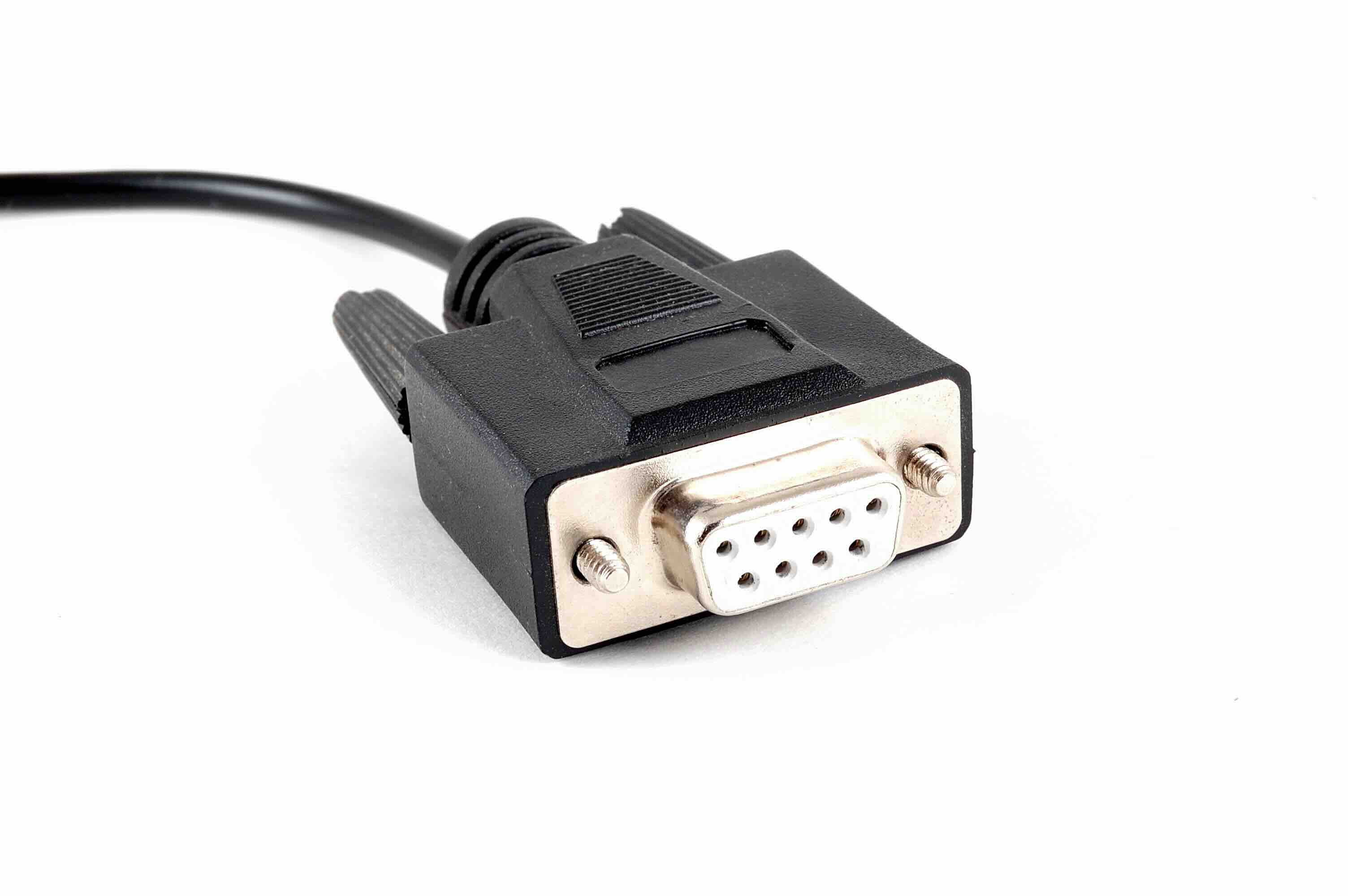
The DB9 is a D-sub connector with nine pins arranged in two rows, five on one side and four on the other. It has been around for decades, originally used heavily in serial RS-232 communications. For CAN bus applications, the connector was adopted because it was already widely available, mechanically solid, and offered enough pins to accommodate the necessary signals plus optional additions. The male connector carries pins and the female carries sockets, and the locking screws on either side of the shell keep the connection secure even in environments where vibration is a constant concern. It is not the only connector type used in CAN bus setups, but it is the one most people encounter when working with CANopen devices and industrial equipment following the CiA 303-1 standard.
CAN Bus DB9 Pinout: Pin by Pin Breakdown
The pinout for a CAN bus DB9 connector is defined primarily by the CiA 303-1 recommendation, which has become the de facto standard in industrial applications. Knowing what each pin does is essential for wiring, troubleshooting, and system design. Here is how the pins are typically assigned on the DB9 male connector used in CAN bus implementations:
- Pin 1: Optional, sometimes used for a reference voltage or left unconnected
- Pin 2: CAN Low (CAN_L) -- this is one of the two differential signal lines
- Pin 3: Ground (CAN_GND) -- signal reference ground
- Pin 4: Optional, sometimes used for additional ground or shielding
- Pin 5: Optional, sometimes used for CAN shield
- Pin 6: Ground (CAN_GND) -- additional ground connection
- Pin 7: CAN High (CAN_H) -- the second differential signal line
- Pin 8: Optional, sometimes reserved for bus voltage supply
- Pin 9: Optional, sometimes used for a 9V or 24V power supply line depending on the implementation
Pins 2 and 7 are the workhorses of the connection. CAN_L and CAN_H together carry the differential signal that makes CAN bus so noise-resistant. Pins 3 and 6 provide grounding. The remaining pins vary by manufacturer and application, which is worth paying attention to before assuming a generic cable will work in a specific setup.
Key Advantages of Using DB9 for CAN Bus
There are real practical reasons the DB9 became a go-to connector format for CAN bus deployments, especially in industrial and automation contexts. It is not just legacy inertia driving its continued use.
- Wide availability and low cost make sourcing replacements straightforward in nearly any part of the world
- The mechanical locking screws provide reliable retention in high-vibration environments where a loose connection could cause system failures
- The nine-pin layout offers enough additional pins for optional power delivery or shielding beyond the two core signal lines
- Compatibility with the widely adopted CiA 303-1 standard means devices from different manufacturers interoperate predictably
- The connector is gender-neutral in terms of sourcing, meaning both male and female variants are easy to find in various cable lengths and configurations
For applications that require a proven, standardized physical interface that technicians already understand and can work with quickly, the DB9 hits a practical sweet spot that newer connector formats have not fully displaced.
Common Drawbacks and Limitations to Know About
It is fair to say the DB9 is not a perfect solution for every CAN bus application. There are situations where its limitations become relevant. The connector is relatively large compared to modern alternatives, which can be a problem in space-constrained enclosures or densely packed control panels. The optional pins, while flexible, also introduce inconsistency. Two devices labeled as CAN bus DB9 might use those optional pins in completely different ways, which can cause confusion or compatibility issues if you are not careful about checking the specific documentation for each device. Additionally, the DB9 does not inherently support hot-swapping well, so connecting or disconnecting devices while the network is live is not recommended without proper precautions. In harsh outdoor environments, the standard DB9 shell is not rated for the same ingress protection levels as some alternative connector formats designed specifically for field use.
Termination Resistors and Why They Are Critical
One topic that comes up constantly when working with CAN bus and DB9 connections is termination. CAN bus networks require 120-ohm termination resistors at each end of the bus to prevent signal reflections that would corrupt data transmission. This is not optional and it is not something you can skip to see if it works. In practice, what this means for DB9 connectors is that when you are wiring up a CAN bus segment, the devices at each physical end of the network need termination either built in or added externally. Some DB9 CAN bus connectors and adapters come with integrated termination resistors, which is a convenient feature worth looking for. Others require you to add them manually. Getting termination wrong is one of the most common causes of CAN bus communication errors, so it deserves serious attention during installation and testing.
Practical Tips for Working With CAN Bus DB9 Connections
Whether you are installing a new CAN bus system or maintaining an existing one, a few practical habits make the work go a lot smoother. Always verify the pinout documentation for every specific device rather than assuming it follows the standard exactly. Use a multimeter to confirm continuity and correct wiring before powering up. Twisted pair cable for CAN_H and CAN_L lines significantly reduces noise pickup over longer cable runs, so do not cut corners on cable quality. Label connectors and cables clearly because DB9 connectors look identical from the outside regardless of what they are carrying. If you are building custom cables, double-check that your connector shell is properly shielded and grounded where the application demands it. And if you are adding devices to an existing network, check total bus length and node count against the specifications for your chosen baud rate before assuming everything will just work.
Why Monoprice Is a Smart Choice for Your CAN Bus and Connectivity Needs
When you are sourcing cables, connectors, and networking components for serious applications, quality and value need to coexist. That is where Monoprice industrial and networking cables and connectivity solutions genuinely stand out. Monoprice has built a well-earned reputation for delivering high-performance components at prices that make sense for both individual technicians and procurement teams managing larger deployments. The product range covers the kind of reliable, well-built connectivity hardware that CAN bus and industrial network applications demand, without forcing you into the inflated pricing that comes with some specialty suppliers. Whether you need shielded cables, D-sub connectors, or the supporting hardware to build out a clean, professional installation, Monoprice brings the same value-driven approach to connectivity that engineers and integrators depend on. It is the kind of sourcing decision that holds up over time.
Frequently Asked Questions About CAN Bus DB9 Connectors
What is the standard pinout for a CAN bus DB9 connector?
The most widely used standard is the CiA 303-1 recommendation, which assigns CAN_L to pin 2, CAN_GND to pin 3, CAN_H to pin 7, and additional ground to pin 6. Other pins are optional and vary by manufacturer.
Is the DB9 connector the only option for CAN bus connections?
No. While DB9 is common in industrial and CANopen applications, other connector types including M12, open-wire terminal blocks, and proprietary connectors are also used depending on the application and environment.
Why are there two ground pins on a CAN bus DB9 connector?
Having two ground pins, typically pins 3 and 6, provides redundancy and supports better shielding practices. Some implementations use one for signal ground and one for chassis or shield ground.
What cable should I use with a CAN bus DB9 connector?
Use shielded twisted pair cable with the CAN_H and CAN_L lines twisted together. This minimizes electromagnetic interference and maintains signal integrity, especially over longer cable runs.
Do I need termination resistors with every DB9 CAN bus connection?
Termination resistors are required at both physical ends of the CAN bus network, not at every node. The standard value is 120 ohms. Without proper termination, signal reflections will cause communication errors.
Can I use a standard DB9 serial cable for CAN bus?
No. Standard RS-232 serial cables use a different pinout and are not wired for differential CAN bus signals. Using the wrong cable will result in failed communication and could damage devices.
What is the maximum cable length for a CAN bus network using DB9 connectors?
Maximum cable length depends on baud rate. At 1 Mbit/s the practical limit is around 40 meters. At lower speeds like 125 Kbit/s you can extend the network to approximately 500 meters or more.
How many devices can connect to a single CAN bus network?
The CAN bus protocol theoretically supports up to 2048 different message identifiers, but practical node limits are typically around 110 to 127 nodes per network segment depending on driver specifications and bus loading.
What does differential signaling mean in the context of CAN bus?
Differential signaling means the data is transmitted as the voltage difference between two wires, CAN_H and CAN_L, rather than as a voltage level on a single wire. This makes the signal highly resistant to common-mode noise and interference.
How do I troubleshoot a CAN bus network connected via DB9 connectors?
Start by verifying correct pinout wiring, checking that termination resistors are present and correctly valued at both ends of the bus, confirming ground connections are solid, and using a CAN bus analyzer or oscilloscope to inspect signal quality on the CAN_H and CAN_L lines.


